

Fundamentals of a Code-Compliant Gas Line Pressure Test
To perform a code-compliant gas line pressure test, isolate the system at the meter, cap every appliance drop and open outlet, install a calibrated test gauge, and pressurize the line with clean compressed air or nitrogen to the pressure required by your local code—commonly 10 to 20 psig for residential work. Let the pressure stabilize for 5 to 10 minutes, then hold it for at least 10 minutes while watching for any drop. Spray every exposed joint with bubble leak-detection solution, and only after the line holds steady and passes inspection should you depressurize and reconnect appliances.
Performing a gas line test requires understanding the physics of pressurized fluids and adhering strictly to established engineering standards. Whether dealing with a newly installed distribution run or a simple residential modification, safety codes such as the International Residential Code (IRC) Section G2417.4 and ASME B31.3 dictate exact parameters for testing fuel gas systems. The overarching principle is straightforward: never introduce flammable natural gas or propane into an untested or unverified piping network.
To maintain high safety margins, international standards outline clear criteria for evaluating pipe assemblies under stress. Adhering to recognized guidelines for field pressure testing piping systems ensures that every joint, valve, and fitting has the structural integrity required to operate safely for decades without risking catastrophic failure or slow, hazardous leaks.
Differentiating Leak Testing vs. Proof Testing
Pressure testing falls into two primary categories: proof testing and leak testing. While they might seem identical on the surface, they serve entirely different safety functions.
- Proof Testing: A proof test verifies the mechanical integrity and structural strength of the piping material and its joints. This test is conducted at pressures significantly higher than the standard operating limits—typically ranging from 110% to 150% of the Maximum Allowable Working Pressure (MAWP). For example, industrial piping under ASME B31.3 often requires hydrostatic proof pressures reaching 1.5 times the design limit to ensure materials will not rupture under unexpected pressure spikes.
- Leak Testing: A leak test confirms containment integrity and joint tightness under normal or slightly elevated operating conditions. Its objective is to ensure that no micro-fissures, thread imperfections, or faulty fusion joints exist that could allow fuel gas to seep into enclosed spaces. In residential settings, testing focuses primarily on leak tightness at code-mandated baselines before any fuel gas enters the system.
Hydrostatic vs. Pneumatic Testing Safety Hazards
The two primary testing mediums are liquids (hydrostatic) and gases (pneumatic). Each presents distinct physical properties, operational advantages, and safety hazards:
| Feature / Metric | Hydrostatic Testing | Pneumatic Testing |
|---|---|---|
| Test Medium | Clean water or compatible liquid | Clean dry air, nitrogen, or inert gas |
| Compressibility | Incompressible fluid | Highly compressible gas |
| Stored Energy Level | Low stored mechanical energy | Extremely high stored energy |
| Failure Mode | Localized tear or minor liquid spray | Explosive blast wave with shrapnel potential |
| Typical Test Pressure | 1.5 × MAWP (per ASME B31.3) | Usually lower (1.1 × to 1.5 × MAWP depending on standard) |
| System Suitability | Heavy industrial lines tolerant of moisture | Interior fuel gas, cryogenic, and residential lines |
Pneumatic testing is inherently more hazardous than hydrostatic testing under identical conditions of volume, temperature, and pressure. When a gas is compressed, it stores tremendous potential energy. If a component fails during a pneumatic test, that energy releases instantly in an explosive decompression, creating shockwaves and throwing sharp debris.
For example, when evaluating polyethylene (PE) distribution lines under the ASTM standard for pneumatic leak testing (ASTM F2786), field technicians must recognize that stored pneumatic energy can equal thousands of horsepower released in fractions of a second. Doubling the pipe diameter quadruples this potential energy release.
Because of this hazard, safety rules dictate that restricted access area requirements apply to any untested system subjected to an internal pressure of 103 kPa (15 psi) or greater. When high-pressure pneumatic tests are executed on large commercial or industrial systems, safety exclusion zones must extend outward—often up to 30 meters (100 feet) or more—to protect personnel from potential burst trajectories.
Essential Equipment, Media, and Setup Procedures
A successful test relies on proper equipment calibration and careful gas medium selection. Pressurizing a line with improper tools or unstable gases can lead to severe accidents or false inspection passes.
When selecting the test medium, code dictates that only clean, dry compressed air, nitrogen, carbon dioxide, or other approved inert gases may be used. Oxygen is strictly prohibited. Under pressure, pure oxygen reacts violently with minute traces of pipe-threading oils, hydrocarbons, or pipe dope, leading to spontaneous auto-ignition and pipe detonation.
The selection of testing gauges is governed strictly by the IRC fuel gas piping pressure test requirements. A frequent reason tests fail municipal inspections is gauge scale mismatch:
- The Five-Times Gauge Rule: The face of a mechanical pressure gauge must not have a maximum scale exceeding five times the intended test pressure. If you are conducting a standard 20 psig residential test, using a 0–300 psig gauge is a code violation. The scale increments on an oversized gauge are too broad to reveal a slow 1-psig drop over a 10-to-15-minute test window.
- Gauge Increments: Mechanical test gauges must feature clean, readable gradations (typically 0.2 to 2 psig increments depending on test scale) or use digital manometers calibrated to tenths of a pound per square inch.
Tool Selection and Test Manifold Configuration
A proper pressure test manifold acts as the control center during the procedure. It allows the technician to introduce pressure safely, monitor stability, isolate the compressor, and bleed pressure off gradually once testing concludes.
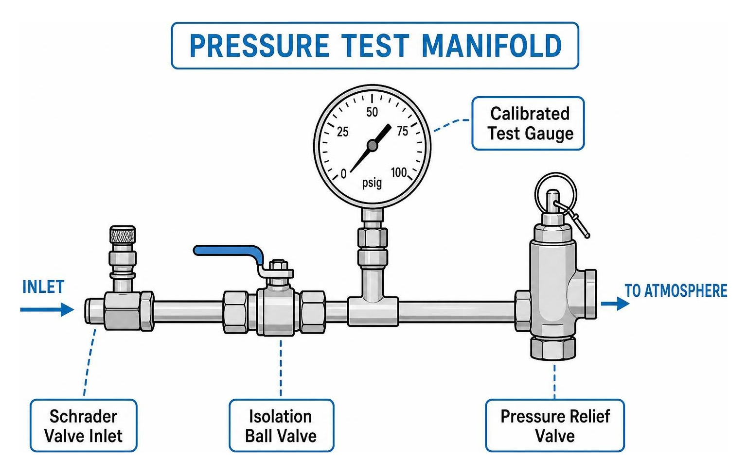
A professional test assembly includes:
- A Calibrated Test Gauge or Digital Manometer: Sized correctly to the test range and checked regularly for accuracy.
- Schrader Valve Inlet: Allows controlled connection to a manual hand pump, nitrogen cylinder regulator, or small air compressor.
- Isolation Ball Valve: Isolates the pressurization source from the piping network, preventing air from leaking back through a faulty compressor check valve during the hold period.
- Pressure Relief Mechanism: A calibrated pop-off relief valve set just above the target test pressure prevents accidental over-pressurization of fragile pipe sections.
- Bleed-Off Valve: Allows safe, controlled depressurization of the system following inspection.
Safety Distances and Job Safety Analysis (JSA)
Before attaching the test manifold, technicians complete a Job Safety Analysis (JSA) to identify hazards, inspect all pipe materials, and verify end-cap restraints.
- Establishing the Exclusion Zone: Calculate blast buffer radiuses using ASME PCC-2 formulas for high-pressure setups. For low-pressure residential tests under 20 psig, clear all unauthorized people, homeowners, and non-essential crew members from the immediate room or trench.
- Personal Protective Equipment (PPE): Everyone inside the testing perimeter must wear ANSI-approved eye protection, impact-resistant gloves, steel-toed footwear, and hard hats.
- Securing End Closures: High-pressure tests require mechanical thrust blocks or welded/fused end-caps. Unrestrained slip-on caps or temporary compression fittings can blow off with lethal velocity under pressure.
Step-by-Step Guide to Executing and Documenting the Test
Testing a fuel gas system requires discipline, patience, and meticulous attention to detail. Skipping a step or rushing the pressurization phase can ruin a test or cause structural pipe damage.
If an older or heavily worn line fails to hold pressure due to widespread thread decay or concealed damage, reviewing gas line repair and replacement cost factors helps determine whether targeted pipe remediation or a complete supply re-pipe is the most practical path forward.
How to Execute a Residential Gas Line Pressure Test Step-by-Step
Executing a safe, code-compliant residential pressure test follows a clear procedural framework:
- Isolate the System Completely: Close the upstream gas meter valve and lock it out if necessary. Disconnect all downstream gas-fired appliances (water heaters, furnaces, ranges) at their individual fixture shut-off valves or disconnect the flexible appliance connectors and cap the drops. Never test against an appliance gas control valve. Appliance regulators are designed for inches of water column (less than 0.5 psig); hitting them with 10 to 20 psig can rupture their internal rubber diaphragms and ruin the appliance.
- Cap and Plug Outlets: Ensure all open fuel outlets, fireplace drops, and stub-outs are securely sealed with threaded malleable iron caps or plugs coated in gas-rated PTFE tape or pipe thread sealant.
- Install the Test Assembly: Thread your calibrated test manifold into an accessible port—often at the exterior riser near the meter location or an exposed rough-in branch.
- Pressurize in Incremental Stages: Connect your air supply or nitrogen cylinder. Introduce pressure gradually. Bring the system up to approximately 50% of the target pressure, then pause for two minutes to check for major audible leaks or rapid gauge drop-offs. If stable, bring the line up to the final required test pressure (typically 10 to 20 psig for residential lines, or local code baseline).
- Allow for Temperature Equalization: When gas is compressed into a confined pipe, its temperature rises slightly. As the gas cools inside the pipe, pressure will drop slightly according to the Ideal Gas Law ($PV = nRT$). Allow the system to stabilize for 5 to 10 minutes before recording your official starting pressure.
- Conduct the Official Hold Period: Start your timer. The minimum hold duration for standard residential piping under the IRC is 10 minutes, though many municipal codes mandate 15, 30, or 60 minutes. Monitor the gauge closely. The needle must remain completely motionless throughout the hold duration.
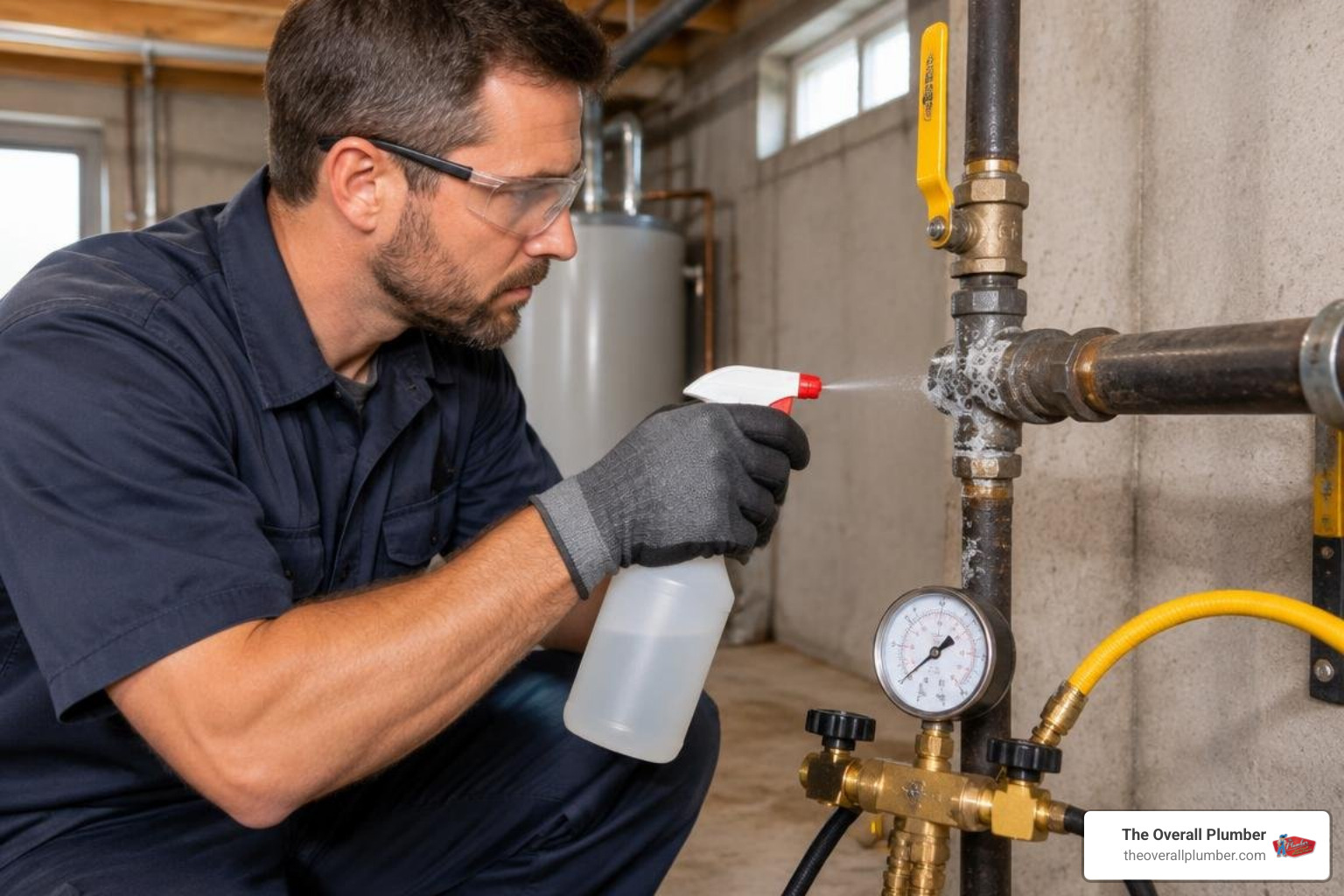
- Inspect All Exposed Joints: While the line is under pressure, spray every joint, fitting, valve body, and union with an approved non-corrosive bubble leak-detection solution. Look for expanding foam or distinct bubbling patterns. If pressure drops or bubbles appear, utilize verified methods to fix gas pipe leaks quickly, rebuild the compromised fitting, and restart the test from the beginning.
- Depressurize and Disassemble: Once the hold time is satisfied and verified by an inspector, open the bleed valve slowly to release the pressurized air. Never unscrew a test manifold or plug while the line is under pressure.
When Is a Utility-Mandated Gas Line Pressure Test Required?
A pressure test is not just for brand-new construction. Utilities and municipal inspectors require a certified test across multiple real-world scenarios:
- Meter Lockouts and Inactive Service: When gas service has been shut off or locked out by the utility for an extended period (typically 6 to 12 months), a safety test must be completed and passed before service is restored.
- Permit Clearances for Remodels: Adding a branch for an outdoor kitchen, converting to a tankless water heater, or adding a gas fireplace requires permits and an official test witnessed by a city inspector.
- Post-Disaster and Emergency Restorations: After major storms, floods, or suspected ground movement, gas utilities lock meters until a licensed plumber verifies system integrity.
If your meter has been locked, understanding utility meter inspection requirements helps you coordinate required city permits, pressure checks, and utility release schedules smoothly. For homes throughout our service areas, following established regional inspection guidelines in Houston prevents unnecessary utility reconnection delays.
Documenting Test Reports and Returning Systems to Service
Documentation is essential for passing inspection and establishing a verifiable safety record:
- Test Documentation: Record the date, permit number, test medium used (e.g., compressed air or nitrogen), starting pressure, ending pressure, ambient temperature, hold duration, and technician certification details. Many jurisdictions require time-stamped photographs of the gauge at the start and end of the hold window.
- System Purging: After passing inspection, remove the test manifold, reconnect all gas supply lines to the utility meter, and remove caps at appliance drops. Slowly open the main gas supply valve.
- Purging Trapped Air: Vent the inert air from the piping system through an open-air vent or appliance branch until clean, unadulterated natural gas or LP flows through the line.
- Live-Gas Sniff Check: Reconnect all appliances using new flexible connectors. Turn on the gas stops and perform a live sniff check using an electronic combustible gas detector and bubble solution on every final hook-up joint. Relight appliance pilots following manufacturer procedures and confirm proper operating pressures.
Frequently Asked Questions About Gas Line Pressure Testing
What is the minimum pressure and hold time required for a residential gas line test?
Under the standard International Residential Code (IRC Section G2417.4), the minimum test pressure must be at least 1.5 times the maximum working pressure of the system, but never less than 3 psig. The minimum hold duration is 10 minutes.
However, local jurisdictions and utility service rules frequently adopt stricter requirements. Across many Texas municipalities, local plumbing codes specify testing residential gas systems at 10 to 20 psig for a minimum duration of 15 to 30 minutes to make tiny leaks immediately visible on mechanical gauges. Always check local city amendments before setting your test pressure.
Why is oxygen prohibited as a test medium for gas piping?
Oxygen must never be used to pressurize any fuel gas piping system. When pure oxygen is compressed into a fuel line, it comes into contact with pipe-threading compounds, residual lubricating oils, or hydrocarbon residues.
Under pressure, oxygen lowers the auto-ignition point of these hydrocarbons, leading to immediate combustion or violent pipe explosions without any external spark. Always use clean compressed air, nitrogen, or inert carbon dioxide.
Can a homeowner perform their own gas pressure test without a licensed professional?
While a handy homeowner might physically assemble a pressure gauge, municipal permitting offices and natural gas utilities will not accept a test report or release a gas meter without an inspection tied to a permit pulled by a licensed professional.
Fuel gas testing carries high liability, complex code mandates, and severe safety hazards. If done incorrectly, over-pressurization can rupture hidden pipe joints or damage expensive appliance valves, creating dangerous fire hazards.
To ensure your fuel lines pass city inspection on the first visit and keep your property fully protected, turn to a certified plumber for gas system testing. Our team delivers thorough safety inspections, accurate pressure verifications, and gas line repairs backed by satisfaction guarantees, priority scheduling, and transparent service with no overtime fees or trip charges across Houston, Brazoria County, Harris County, Galveston County, and surrounding communities.
Ready to test, repair, or restore your gas service safely? Call The Overall Plumber today.